
OSENC Magnetic Separation
Custom Magnetic Assemblies and Magnetic Circuit Solutions
Confirmed OSENC Core Business
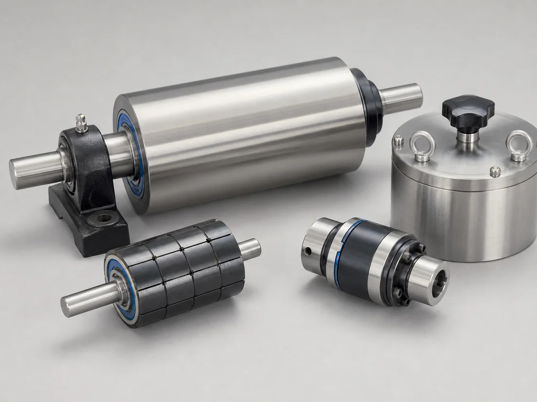
We support drawing-based magnetic assemblies that combine magnets with steel, stainless steel, shafts, housings, adhesives, fasteners, and other components. Projects can include magnetic drums, rollers, wheels, rotors, couplings, Halbach arrays, and other custom steel-and-magnet systems.
Assembly Types
- Magnetic drums and rollers
- Magnetic wheels and pulley components
- Halbach arrays
- Magnetic couplings
- Magnetic rotors
- Custom steel-and-magnet assemblies
- OEM magnetic modules developed from a drawing or sample
Why the Complete Magnetic Circuit Matters
A magnet grade does not define the final assembly field by itself. Steel grade and thickness, pole shape, air gap, magnet orientation, leakage, operating temperature, neighboring components, and assembly tolerance can all change performance. A design review can include magnetic analysis and coordinated simulation where appropriate; the model assumptions and predicted result should be linked to the drawing and verified against an agreed test whenever practical.
Project Inputs
- Assembly drawing and available envelope
- Required field, force, torque, or coupling behavior
- Measurement position and air gap
- Rotational speed, mechanical load, and balance requirement
- Working temperature, corrosion, impact, and vibration
- Magnet material and pole orientation
- Steel and non-magnetic component requirements
- Quantity, sample plan, and expected production volume
- Acceptance test and required documents
Manufacturing Coordination
OSENC is an independent magnetic solutions supplier, not the owner of every production process. Machining, welding, coating, magnet production, assembly, and specialized testing may be arranged through qualified partner facilities. The manufacturing route should be selected for the drawing, quantity, tolerance, and quality requirement.
Assembly Risks Reviewed Early
- Magnet breakage during press-fit or fastening
- Adhesive gap and curing conditions
- Incorrect pole orientation
- Steel saturation or excessive leakage
- Corrosion at interfaces
- Rotor imbalance or runout
- Unsafe attraction during assembly and transport
- Tolerance stack changing the working air gap
Prototype and Approval Process
- Application and drawing review
- Magnetic and mechanical proposal
- Manufacturing and inspection plan
- Prototype or sample assembly
- Dimensional and magnetic verification
- Buyer fit/function approval
- Batch production and lot control
Inspection
Possible checks include dimensions, runout, balance, surface, coating, pole orientation, flux density, total flux, pull force, torque, or a custom functional fixture. The test method must define the instrument, mating part, air gap, direction, speed, and acceptance tolerance.
Documents
Depending on the project, the document package can include drawings, dimensional records, magnetic test reports, material reports, coating reports, RoHS, REACH, MSDS, packing records, and inspection photographs. Availability must be confirmed before order.
Request an Assembly Review
Send the assembly drawing, magnetic requirement, air gap, mechanical load, temperature, environment, quantity, and test method.
Custom Assembly Products and Engineering Services
- Custom Magnetic Rollers: OEM roller geometry, shafts, bearings, pole patterns, runout and field mapping.
- Other custom assemblies can be reviewed from a controlled drawing, magnetic target, mechanical interface and acceptance method without creating separate product pages.
Inputs Required Before a Magnetic-Assembly Design Review
The quotation should describe the complete steel-and-magnet system and connect each proposed feature to an operating or acceptance requirement.
| Selection logic | Choose the magnetic circuit and retention method together; magnet grade alone cannot define field, torque, holding force or safe mechanical duty. |
|---|---|
| Application inputs | Application function, target field or force, working gap, temperature, duty cycle, loads, tolerances and quantity |
| Mechanical interface | Provide mating components, shafts, bearings, fasteners, adhesive zones, balance or runout limits and installation envelope. |
| Cleaning and service | Define assembly handling, service access and replacement method where magnets can attract tools, debris or neighboring steel. |
| Acceptance method | Agree drawing dimensions, material traceability, magnetic map or force method, runout or balance checks and sample validation. |
Engineering Conditions Behind the Recommendation
- A drum result depends on field strength and gradient through the shell and actual material path, not on magnet grade alone.
- Feed distribution, layer depth, particle size and magnetic response, drum diameter and speed, magnetic arc, splitter position and discharge trajectory must be evaluated together.
- Mechanical passage capacity is not the same as effective separation capacity.
- Quote or test conditions must identify material, size distribution, moisture, bulk density, normal and peak rate, feed distribution, speed, layer or flow geometry, contamination loading and cleaning interval.
What We Need to Configure This Project
Input set for Custom Magnetic Assemblies and Magnetic Circuit Solutions
- How we use your data: We compare your material, contamination risk, production target and line interface before we configure a proposal or rule out an unsuitable option.
- Material: name and composition; dry or wet; powder, granule, lump, fibre or slurry; minimum, maximum and typical particle distribution; moisture, stickiness, tendency to cake or bridge, abrasiveness, corrosiveness, bulk density, normal temperature and maximum temperature.
- Production and target: normal and peak throughput, continuous or batch feed, feed uniformity, contaminant or recovery target, magnetic response if known, typical and maximum target size, initial concentration, acceptable residual and whether product loss is permitted.
- Installation: feed chute and discharge geometry, drum or pulley diameter and working width, shaft/bearing interface, speed, splitter space, drive arrangement and maintenance access; cleaning method, permitted shutdown, contact-material, wear and corrosion requirements; indoor, outdoor, washdown, high-humidity, dusty or hazardous-area conditions.
- Supporting project files: drive voltage, frequency, phase and control interface; state whether any pneumatic actuator or air service is required; destination country; current drawings, site photographs, running video and a representative material/contaminant sample when testing is needed.
- What you receive next: We use the confirmed inputs to prepare a project-specific drawing and inspection plan. We do not treat performance as confirmed until the agreed design and any required representative test or site acceptance establish the result.
Project Support
Send your drawing, material data or installation photo
We will review the product structure, magnetic circuit direction, cleaning method, material contact requirements and inspection items before preparing a quotation.
Frequently Asked Questions
Why the Complete Magnetic Circuit Matters?
A magnet grade does not define the final assembly field by itself. Steel grade and thickness, pole shape, air gap, magnet orientation, leakage, operating temperature, neighboring components, and assembly tolerance can all change performance.
Why is “Manufacturing Coordination” important for this decision?
OSENC is an independent magnetic solutions supplier, not the owner of every production process. Machining, welding, coating, magnet production, assembly, and specialized testing may be arranged through qualified partner facilities.
Why is “Inspection” important for this decision?
Possible checks include dimensions, runout, balance, surface, coating, pole orientation, flux density, total flux, pull force, torque, or a custom functional fixture.