
OSENC Magnetic Separation
Custom Magnetic Rollers Designed Around the Machine Interface
OEM Rotating Magnetic Components
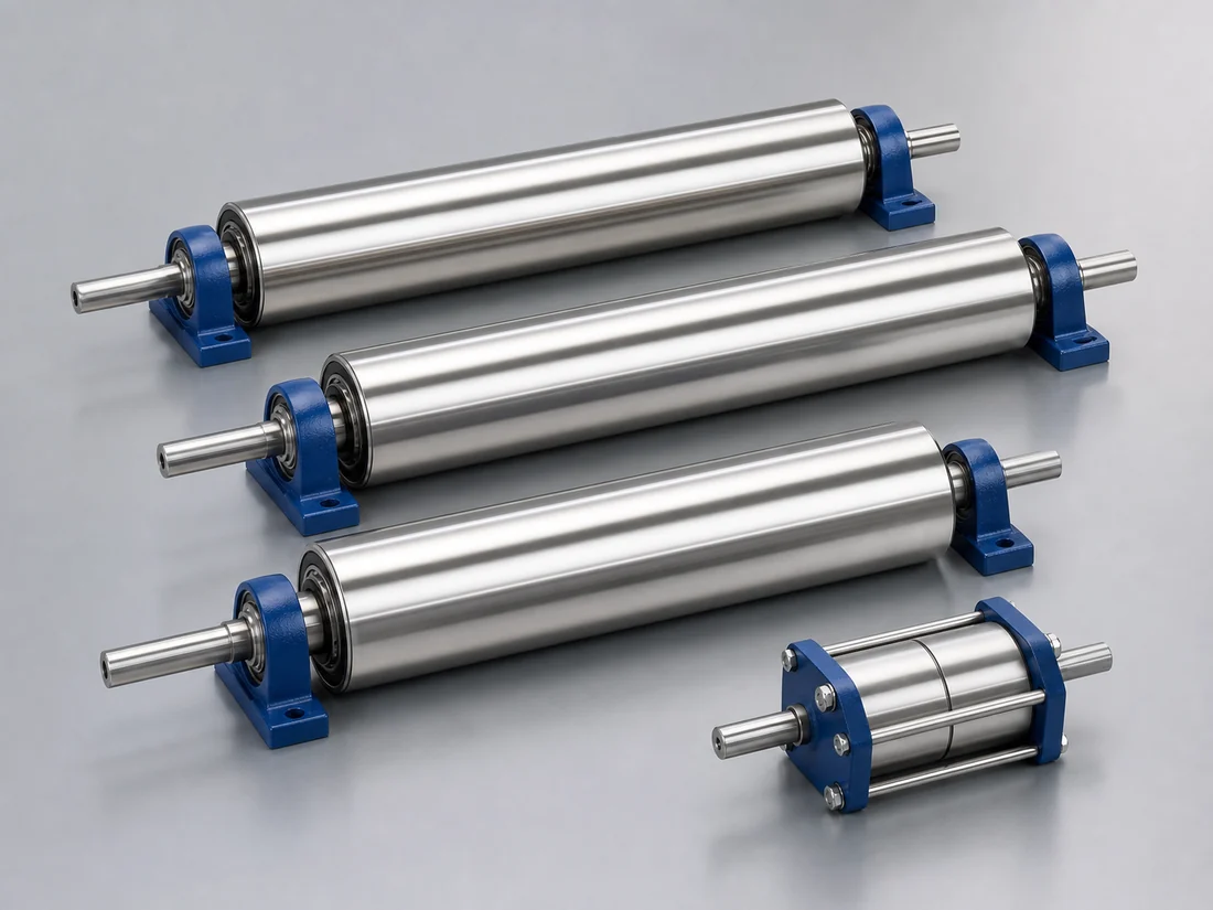
We review custom magnetic rollers from the required field, working gap, diameter, face length, shaft and bearing interfaces, speed, load, surface material, runout, temperature and test method. We cover OEM roller components; conveyor head pulleys and housed magnetic drum separators have separate pages because their process and mechanical responsibilities are different.
Define the Roller Function First
State whether the roller attracts, holds, transfers, positions, separates, senses or provides a magnetic field to another component. The function determines pole arrangement, active arc, working gap, steel circuit and whether continuous field around the circumference is needed.
Mechanical Inputs
| Input | Why it matters |
|---|---|
| Diameter and face length | Envelope, magnetic volume, surface speed and stiffness |
| Shaft ends and datums | Drive, bearing, alignment and replacement fit |
| Bearing arrangement | Load, speed, sealing, heat and maintenance |
| Surface | Stainless shell, coating, lagging, wear and product contact |
| Runout and balance | Air-gap stability, vibration and equipment life |
| Torque and load | Shaft, keys, coupling, shell and support design |
Magnetic Pattern
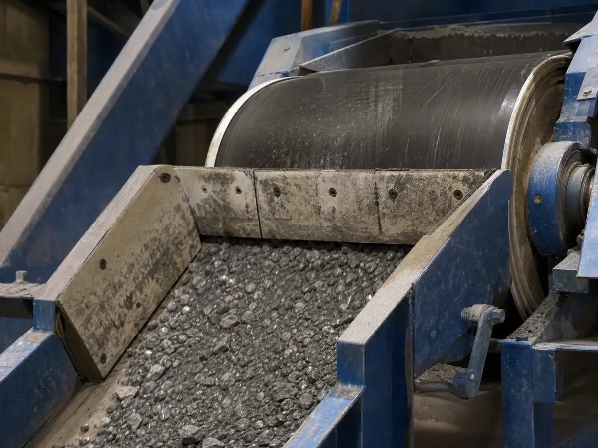
Define active width, pole pitch, number of poles, magnetic arc, radial or application-specific direction, required field at the working gap and nearby steel. A high surface reading may not produce the desired field at the product or sensor. Use a mapped acceptance method tied to the assembled roller.
Speed, Heat and Retention
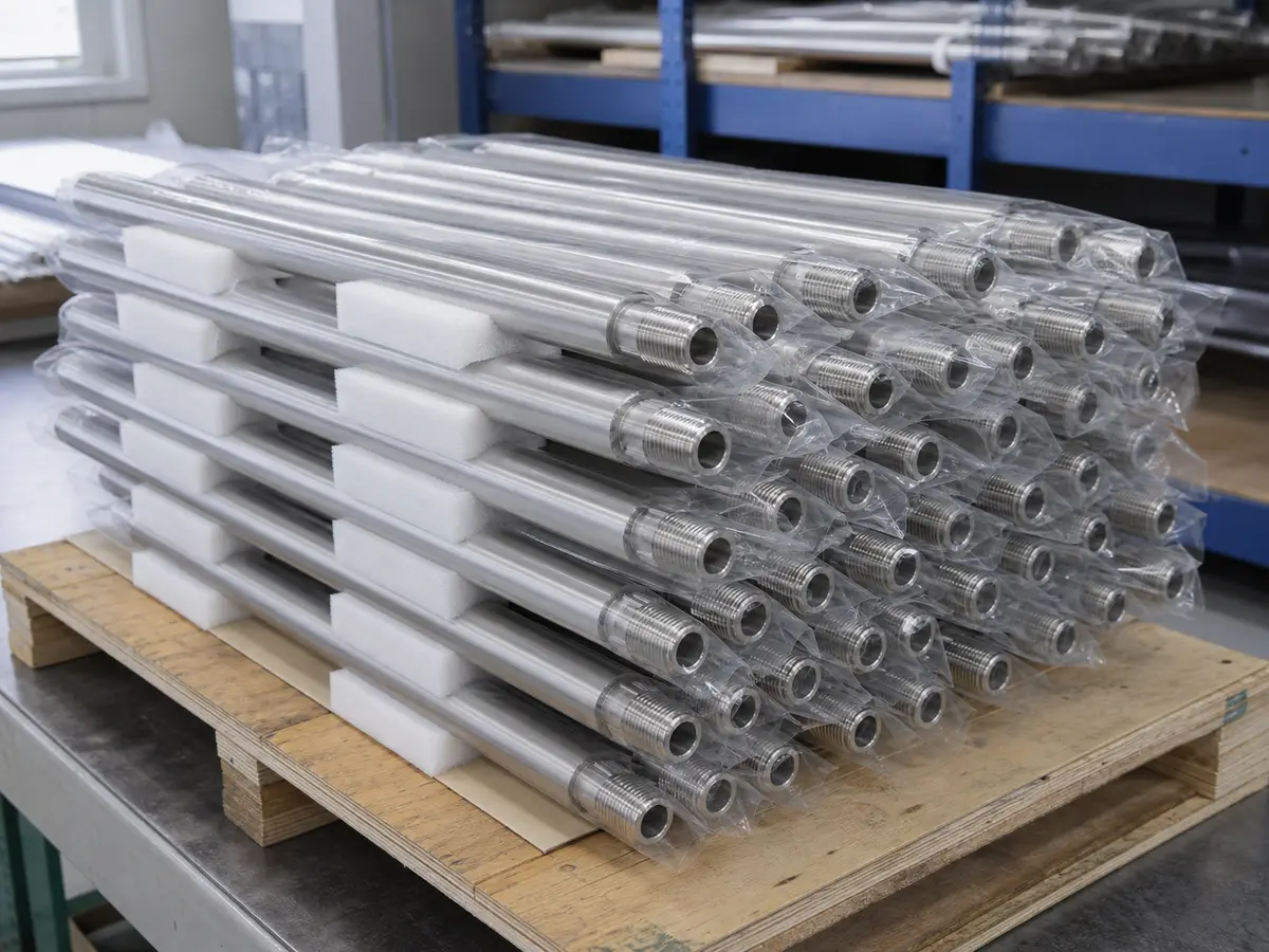
Rotation creates centrifugal, fatigue, vibration and heating concerns. Magnets, adhesive, steel retainers, sleeves and end structures must be reviewed for maximum speed, duty, acceleration, temperature and fault conditions. Maximum speed must be confirmed for the specific roller diameter, mass, retention method, shaft, bearings, balance grade, temperature, and duty cycle.
Manufacturing and Assembly Route
- Approve functional and interface drawings.
- Review magnetic circuit and mechanical retention.
- Confirm machined parts, magnet grade, coating and assembly sequence.
- Build tooling for alignment, bonding or magnetized assembly.
- Inspect dimensions, runout, magnetic map and mechanical condition.
- Perform balance or no-load tests only when specified and available.
Machining, coating, assembly and testing may be coordinated through qualified partners; the quotation should identify the route and deliverables.
Inspection and Acceptance
- Interface dimensions, shaft features, face and datums
- Runout, straightness or balance under agreed conditions
- Surface, coating, shell, weld and adhesive condition
- Polarity, pole pitch, active width and field map
- Rotation direction and functional fixture test
- Materials, components and reports within scope
When Another Product Fits Better
- Conveyor pulley separation: review a magnetic head pulley.
- Enclosed free-fall separation: review a housed magnetic drum.
- For other custom field arrangements, start from the custom magnetic assemblies page.
RFQ Details
Send assembly and roller drawings, function, working gap, field target, diameter, face, shaft/bearings, speed, load, temperature, surface, environment, runout/balance, rotation, magnetic test, quantities and expected service.
Custom Magnetic-Roller Design Inputs
The quotation should describe the machine interface and rotating duty and connect each proposed feature to an operating or acceptance requirement.
| Selection logic | Choose diameter, pole pattern and magnetic material together with speed, centrifugal load, heat and target working distance. |
|---|---|
| Application inputs | Application, target material response, working gap, required coverage, temperature, duty, maximum speed and quantity |
| Mechanical interface | Provide shaft drawing, bearings, key or coupling, drive torque, runout, balance, envelope and guarding constraints. |
| Cleaning and service | Define safe handling and service because the roller can attract tools and ferrous debris even when the machine is stopped. |
| Acceptance method | Agree drawing inspection, runout, balance, magnetic coverage or field map and a controlled speed or application test where required. |
Engineering Conditions Behind the Recommendation
- Do not select from a surface Gauss value alone.
- Review field strength and gradient at the rated working distance, including the conveyor belt, burden depth and any protective plate.
- Belt speed, feed uniformity, target size, shape and magnetic response determine how much time and force are available for capture.
- Mechanical passage capacity is not the same as effective separation capacity.
- Quote or test conditions must identify material, size distribution, moisture, bulk density, normal and peak rate, feed distribution, speed, layer or flow geometry, contamination loading and cleaning interval.
What We Need to Configure This Project
Input set for Custom Magnetic Rollers Designed Around the Machine Interface
- How we use your data: We compare your material, contamination risk, production target and line interface before we configure a proposal or rule out an unsuitable option.
- Material: name and composition; dry or wet; powder, granule, lump, fibre or slurry; minimum, maximum and typical particle distribution; moisture, stickiness, tendency to cake or bridge, abrasiveness, corrosiveness, bulk density, normal temperature and maximum temperature.
- Production and target: normal and peak throughput, continuous or batch feed, feed uniformity, contaminant or recovery target, magnetic response if known, typical and maximum target size, initial concentration, acceptable residual and whether product loss is permitted.
- Installation: belt width and speed, normal and maximum burden depth, magnet position and rated working distance, available suspension and maintenance space, support and lifting arrangement; cleaning method, permitted shutdown, contact-material, wear and corrosion requirements; indoor, outdoor, washdown, high-humidity, dusty or hazardous-area conditions.
- Supporting project files: drive voltage, frequency and phase where a self-cleaning unit is considered; control interface and any site air requirement; destination country; current drawings, site photographs, running video and a representative material/contaminant sample when testing is needed.
- What you receive next: We use the confirmed inputs to prepare a project-specific drawing and inspection plan. We do not treat performance as confirmed until the agreed design and any required representative test or site acceptance establish the result.
How We Turn This Product into a Project Proposal
Custom Magnetic Rollers Designed Around the Machine Interface: seller-side application review
- Your buying problem: A catalogue name does not confirm that the magnetic circuit, capacity, cleaning method and installation envelope fit your material or production line.
- What we review: We confirm your material, particle size, moisture, temperature, throughput, contaminant type and size, working distance, interfaces, space, environment and cleaning frequency.
- What we supply: After feasibility and drawing approval, we configure the product scope and coordinate manufacturing and inspection through the appropriate qualified resources.
- Buyer value: This helps you avoid blockage, missed contamination, difficult maintenance, interface rework and paying for magnetic performance that cannot be used at the real working gap.
- Boundary: We do not treat website dimensions, Gauss, capacity, certification or lead time as final until they are confirmed in project documents.
- Next step: Send the material and target, particle range, moisture, temperature, throughput, contamination, installation drawing, available space, cleaning preference and any sample or site video. Send your material and interface data
Project Support
Send your drawing, material data or installation photo
We will review the product structure, magnetic circuit direction, cleaning method, material contact requirements and inspection items before preparing a quotation.
Frequently Asked Questions
Why is “Define the Roller Function First” important for this decision?
State whether the roller attracts, holds, transfers, positions, separates, senses or provides a magnetic field to another component.
Why is “Magnetic Pattern” important for this decision?
Define active width, pole pitch, number of poles, magnetic arc, radial or application-specific direction, required field at the working gap and nearby steel.
Why is “Speed, Heat and Retention” important for this decision?
Rotation creates centrifugal, fatigue, vibration and heating concerns. Magnets, adhesive, steel retainers, sleeves and end structures must be reviewed for maximum speed, duty, acceleration, temperature and fault conditions.