
OSENC Magnetic Separation
Permanent Suspended Magnet for Conveyor Tramp-Iron Removal
Manual-Clean Conveyor Protection
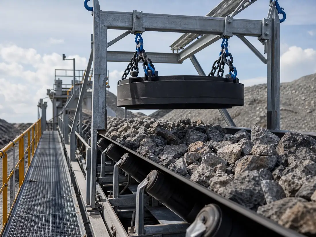
A permanent suspended magnet is installed above a conveyor to attract exposed ferrous tramp such as bolts, tools, wire, nails, or steel fragments. Choose a manual-clean version when contamination is occasional, the conveyor can be safely stopped, and operators can remove collected iron before buildup reduces performance.
Send Belt and Tramp-Iron Details Compare Self-Cleaning Overband
Quick Application Check
- Best for
- Occasional strongly magnetic tramp iron on a conveyor.
- Cleaning
- Manual removal during an isolated, planned stop.
- Power
- The permanent magnetic circuit requires no excitation electricity.
- Main inputs
- Belt width, burden depth, speed, suspension height, material, and target iron.
- Review carefully
- Deep burden, fast belt, frequent iron, hot material, large surges, and unsafe access.
How It Works
The magnetic circuit projects a field toward the moving material. Responsive iron is attracted upward, leaves the burden, and remains on or near the magnet face until cleaning. The field and attraction decrease with distance; iron at the bottom of the burden is harder to remove than iron on top.
Standard Configuration Range
| Item | Standard offering |
|---|---|
| Conveyor belt width | 500, 650, 800, 1,000, 1,200, 1,400 and 1,600 mm |
| Rated face-to-belt distance | 150–400 mm |
| Belt speed | Up to 3.5 m/s |
| Burden depth | 50–250 mm for standard selection |
| Housing | Welded carbon-steel enclosure with replaceable stainless working-face plate |
| Suspension | Four lifting points with project-selected chain or turnbuckle set |
| Magnetic circuit | Ferrite, rare-earth assisted, or hybrid permanent circuit |
| Normal material temperature | Up to 80°C |
Selection Data Required
| Input | Why it matters |
|---|---|
| Belt width and trough | Defines coverage and installation geometry |
| Normal and peak burden depth | Defines the material the iron must travel through |
| Belt speed | Controls exposure time |
| Target size and shape | Plate, wire, bolt, and compact pieces respond differently |
| Suspension reference | Defines the real working distance |
| Iron frequency | Determines whether manual cleaning is practical |
Inline or Crossbelt Installation
Inline installation near the head pulley can benefit from material opening at discharge, while crossbelt installation removes iron across a moving burden. The better position depends on conveyor structure, headroom, steel idlers, material trajectory, discharge route, and maintenance access. The approved drawing must define the reference height.
Manual Cleaning Procedure
- Stop, isolate, and secure the conveyor under the site procedure.
- Control access and keep loose steel tools away from the magnetic face.
- Collect iron using the approved method without placing hands in pinch zones.
- Inspect buildup, magnet face, suspension, and surrounding structure.
- Record cleaning frequency and adjust before excessive accumulation occurs.
When to Choose Another Product
- Frequent iron or continuous operation: review a self-cleaning overband magnet.
- Continuous separation at belt discharge: review a magnetic head pulley.
- Fine iron in gravity-fed powder: review a magnetic grate or drawer magnet.
- Aluminum, copper, and non-responsive targets require another technology.
Testing and Acceptance
Do not compare a maximum surface Gauss value with another separator’s field at working height. Define field or lifting/pull test position, instrument, target, gap, temperature, tolerance, and responsible party. A safe representative conveyor test should record depth, speed, iron location, and result.
Request Selection
Send belt width, trough, speed, material, bulk density, capacity, normal/peak burden, target iron photographs, proposed position, available height, temperature, operating hours, and cleaning plan.
Permanent Suspended-Magnet Selection Inputs
The quotation should describe tramp steel in material carried on a conveyor and connect each proposed feature to an operating or acceptance requirement.
| Selection logic | Use a manual-clean permanent unit where iron loading is low enough for planned safe cleaning and continuous discharge is not required. |
|---|---|
| Application inputs | Material, largest lump, bulk density, moisture, belt width and speed, deepest burden, target steel size and loading |
| Mechanical interface | Confirm magnet-face height, suspension points, available lifting and cleaning space, discharge containment and downstream equipment position. |
| Cleaning and service | State the permitted stop interval, isolation method, cleaning tool and how collected steel is prevented from falling back into the product. |
| Acceptance method | Test defined steel pieces at the specified working height and useful width rather than accepting only a face-field reading. |
Project Scope and Supply Boundary
Boundary for Permanent Suspended Magnet for Conveyor Tramp-Iron Removal
- We supply manual-clean permanent suspended magnets in the standard configuration range described here.
- The approved drawing fixes belt width and speed, burden depth, rated suspension height, largest tramp-iron size, magnetic circuit, suspension points and structural interface.
- Dimensions, magnetic values, pull force, capacity, separation result, materials, certification, lead time and warranty become project facts only in traceable quotation, drawing, inspection or order documents.
What We Need to Configure This Project
Input set for Permanent Suspended Magnet for Conveyor Tramp-Iron Removal
- How we use your data: We compare your material, contamination risk, production target and line interface before we configure a proposal or rule out an unsuitable option.
- Material: name and composition; dry or wet; powder, granule, lump, fibre or slurry; minimum, maximum and typical particle distribution; moisture, stickiness, tendency to cake or bridge, abrasiveness, corrosiveness, bulk density, normal temperature and maximum temperature.
- Production and target: normal and peak throughput, continuous or batch feed, feed uniformity, contaminant or recovery target, magnetic response if known, typical and maximum target size, initial concentration, acceptable residual and whether product loss is permitted.
- Installation: belt width and speed, normal and maximum burden depth, magnet position and rated working distance, available suspension and maintenance space, support and lifting arrangement; cleaning method, permitted shutdown, contact-material, wear and corrosion requirements; indoor, outdoor, washdown, high-humidity, dusty or hazardous-area conditions.
- Supporting project files: drive voltage, frequency and phase where a self-cleaning unit is considered; control interface and any site air requirement; destination country; current drawings, site photographs, running video and a representative material/contaminant sample when testing is needed.
- What you receive next: We use the confirmed inputs to prepare a project-specific drawing and inspection plan. We do not treat performance as confirmed until the agreed design and any required representative test or site acceptance establish the result.
Project Support
Send your drawing, material data or installation photo
We will review the product structure, magnetic circuit direction, cleaning method, material contact requirements and inspection items before preparing a quotation.
Frequently Asked Questions
How It Works?
The magnetic circuit projects a field toward the moving material. Responsive iron is attracted upward, leaves the burden, and remains on or near the magnet face until cleaning.
Why is “Inline or Crossbelt Installation” important for this decision?
Inline installation near the head pulley can benefit from material opening at discharge, while crossbelt installation removes iron across a moving burden.
Why is “Testing and Acceptance” important for this decision?
Do not compare a maximum surface Gauss value with another separator’s field at working height. Define field or lifting/pull test position, instrument, target, gap, temperature, tolerance, and responsible party.