
OSENC Magnetic Separation
Select a magnetic tube from the installation drawing, effective magnetic length, target contamination, working gap, stainless construction, temperature, end connection and agreed magnetic test. A maximum surface-Gauss number without its measurement position does not define the tube’s performance.
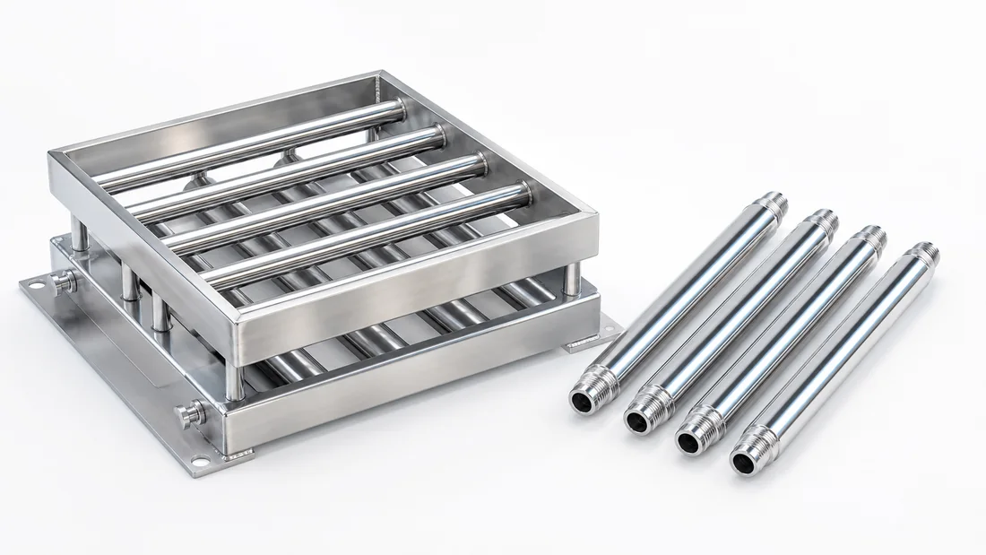
Define the Mechanical Interface
- Outside diameter and overall length
- Effective magnetic length
- Threaded studs, tapped holes, plain ends or custom connection
- Thread size, engagement and orientation
- Required straightness and dimensional tolerances
- Installation drawing and available removal space
Overall length and magnetic length are not necessarily the same. Identify non-magnetic end zones on the approved drawing.
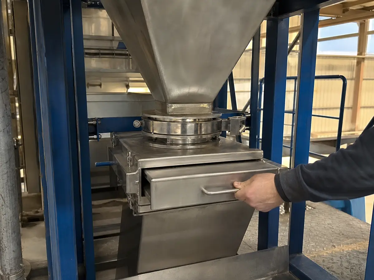
Select the Contact-Surface Material
Specify the shell material based on product compatibility, corrosion, temperature, wear, hygiene and cleaning. Do not write only “stainless steel.” State the grade and which parts it covers. For food-contact applications, also review welds, surface finish, seals and cleaning conditions.

Define Magnetic Performance
State whether the requirement is maximum surface flux density, a field map, pull force or material-capture trial. For a surface reading, define the pole location, probe, orientation and whether the measurement is directly on the shell. For an easy-clean sleeve or protective liner, test at the actual external working surface.
Temperature Is a System Requirement
Provide normal and maximum product and cleaning temperatures, exposure time and cycling. Magnet grade, magnetic circuit, adhesive, seals and shell construction must all tolerate the condition. A high-temperature magnet grade does not automatically qualify the entire tube assembly.
Tube Position and Spacing
Place tubes so material must pass close to active poles without reducing the open area enough to cause bridging. Staggered rows can improve coverage but add pressure drop, hold-up and cleaning work. Validate the layout using the actual particle size and flow behavior.
Cleaning and Inspection
Plan how the tube will be isolated, removed, cleaned and returned to the same position. Fine or sharp captured metal creates handling risk. Establish a visual and repeatable magnetic baseline so damage or loss of performance can be investigated during service.
RFQ Checklist
- Drawing with all lengths and end details
- Material, particle size, flow and temperature
- Target iron description
- Shell grade and surface requirement
- Magnetic test method and limits
- Quantity, inspection level and reports
- Food-contact, RoHS or REACH documents where applicable
When a Tube Alone Is Not Enough
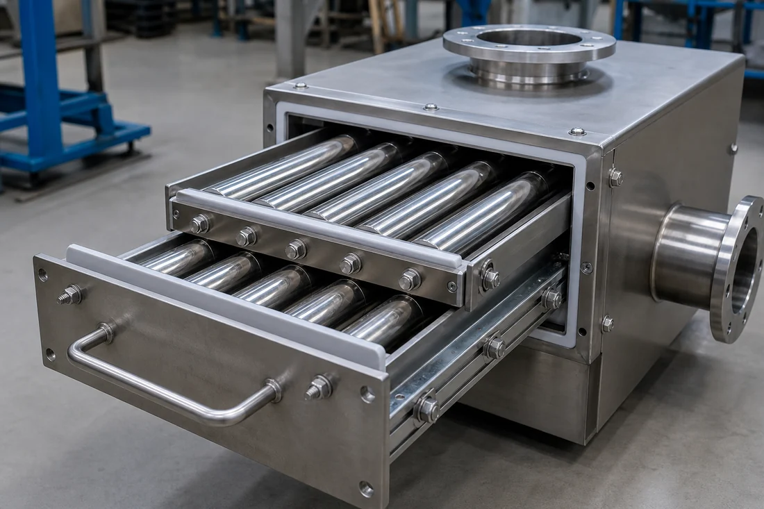
Use a grate for controlled multi-tube coverage, a drawer magnet for an enclosed connection, or an easy-clean structure when frequent cleaning justifies an outer sleeve. Pressure or pneumatic conveying requires a housing and mechanical assessment; do not install an unsupported tube based only on diameter.
Review magnetic tubes Compare tube and grate Request a custom tube review
Minimum RFQ Data for a Magnetic Tube
| Decision rule | Select tube length, pole arrangement and mounting only after confirming that product will pass close enough to the surface without creating an uncontrolled flow path. |
|---|---|
| Inputs to confirm | Material chemistry, particle size, bulk density, moisture, flowability, corrosion, temperature, target iron, peak rate and cleaning interval. |
| Risk or limitation | A high maximum surface value cannot correct poor placement, excessive sleeve distance, bridging or material bypass around the tube ends. |
| Buyer action | Provide the chute or machine drawing, end connection, effective length and agreed field or pull-force test position. |
Engineering Conditions Behind the Recommendation
- A high surface reading does not by itself predict capture in flowing product.
- Field gradient, shell or sleeve thickness, spacing, distance from each particle to a pole, particle size and magnetic response, flow speed, product depth, bridging and contamination buildup all change the result.
- Mechanical passage capacity is not the same as effective separation capacity.
- Quote or test conditions must identify material, size distribution, moisture, bulk density, normal and peak rate, feed distribution, speed, layer or flow geometry, contamination loading and cleaning interval.
What We Need to Configure This Project
Input set for How to Select a Magnetic Tube
- How we use your data: We compare your material, contamination risk, production target and line interface before we configure a proposal or rule out an unsuitable option.
- Material: name and composition; dry or wet; powder, granule, lump, fibre or slurry; minimum, maximum and typical particle distribution; moisture, stickiness, tendency to cake or bridge, abrasiveness, corrosiveness, bulk density, normal temperature and maximum temperature.
- Production and target: normal and peak throughput, continuous or batch feed, feed uniformity, contaminant or recovery target, magnetic response if known, typical and maximum target size, initial concentration, acceptable residual and whether product loss is permitted.
- Installation: hopper, chute or pipeline location, opening or flange dimensions and standard, flow direction, product head, extraction and cleaning space, upstream and downstream connections; cleaning method, permitted shutdown, contact-material, wear and corrosion requirements; indoor, outdoor, washdown, high-humidity, dusty or hazardous-area conditions.
- Supporting project files: power and control data for any actuator or automated cleaning option, plus available air supply and pressure where applicable; destination country; current drawings, site photographs, running video and a representative material/contaminant sample when testing is needed.
- What you receive next: We use the confirmed inputs to prepare a project-specific drawing and inspection plan. We do not treat performance as confirmed until the agreed design and any required representative test or site acceptance establish the result.
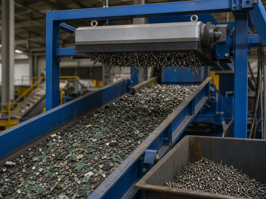
Project Support
Need help selecting the right magnetic solution?
Send us your material, flow condition, target metal, capacity, installation space and any drawings or site photos. We will review the application and recommend the next practical step.
Frequently Asked Questions
Why is “Define the Mechanical Interface” important for this decision?
Overall length and magnetic length are not necessarily the same. Identify non-magnetic end zones on the approved drawing.
Why is “Define Magnetic Performance” important for this decision?
State whether the requirement is maximum surface flux density, a field map, pull force or material-capture trial.
Why is “Temperature Is a System Requirement” important for this decision?
Provide normal and maximum product and cleaning temperatures, exposure time and cycling. Magnet grade, magnetic circuit, adhesive, seals and shell construction must all tolerate the condition.